
In this post, I am going to talk about modelling dc-dc power converters using MATLAB’s user defined function block. Doing so saves a lot of time and it’s much more easier as compared to the Buck converter model in which each dynamical equation is implemented using blocks. Doing so is not only time consuming, but tracking back and finding out errors is hard especially when the system becomes larger. In this model, I have used as few blocks as possible.
The Boost converter circuit is shown in fig.1. I have accounted for the parasitic resistance in passive components as well as the ON resistance for active device.

Fig. 1: Boost converter circuit
Inputs the converter model are:
- Input voltage
- Voltage control (duty cycle)
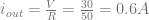
- Load current


Converter outputs:
- Capacitor voltage
- Inductor current
- Output voltage
- Input current


Step 1:
- Start Simulink either using the MATLAB command window or by clicking the Simulink button on the toolbar
- Create a new Simulink model file and save it as boost.mdl
- From the Simulink place 3 instances of constant block located under “commonly used blocks”. Also place a subsystem block as well a scope block.
At this point your model file will look something like fig. 2. Notice that I have renamed the blocks to identify their respective characteristic.

Fig. 2: Initial set up for Boost converter model
Step – 2:
- Open the Boost converter subsystem block by double clicking on it.
Notice the default connection between in1 and out1. Delete this connection.
- Add 2 more instances of In1 and 3 more instance of Out1 found under commonly used block
- Add an instance of subsystem, mux, and demux found under commonly used block
- Navigate to user-defined functions and add a MATLAB Function block to your model file
- Go to the continuous library and add 2 instances of integrator block to your model file.
Make the connections as shown in fig.3 and rename your blocks appropriately. Notice that by default mux block has 2 inputs and demux has 2 outputs. This can be changed by double clicking on the respective blocks and changing the number of inputs/outputs

Fig. 3: Boost converter subsystem block
Step – 3:
- Open the PWM system block, and delete the default connection between In1 and Out1
- Add a repeating sequence block found under Sources
- Go to Math library and add a subtract block
- Finally from the discontinuous library add a relay block and make the necessary connection as shown in fig. 2

Fig. 4: PWM subsystem block
Open the repeating sequence block by double clicking. This block lets you set up switching frequency for the converter as well as the amplitude 

Fig. 5: Setting parameters in repeating sequence block
Step – 4:
Going back to the user defined function, this is where we will enter the converter state equations. You can refer to the boost converter post to get an in-depth view of how these equations are derived.
When the MOSFET 


Similarly, when MOSFET switches off, the equations are


Over one switching period 
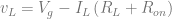
Inductor voltage,
![v_L = \left[V_g - I_L\left(R_L + R_{on}\right)\right]*D + \left(V_g - I_LR_L - V\right)\left(1 - D\right)](https://s0.wp.com/latex.php?latex=v_L+%3D+%5Cleft%5BV_g+-+I_L%5Cleft%28R_L+%2B+R_%7Bon%7D%5Cright%29%5Cright%5D%2AD+%2B+%5Cleft%28V_g+-+I_LR_L+-+V%5Cright%29%5Cleft%281+-+D%5Cright%29&bg=ffffff&fg=666666&s=0&c=20201002)
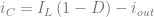
Capacitor current,

Input current,

Output voltage,
![V = \left[v_C - R_{ESR}i_{out}\right]*D + \left[v_C + R_{ESR}\left(I_L - i_{out}\right)\right]*\left(1 - D\right)](https://s0.wp.com/latex.php?latex=V+%3D+%5Cleft%5Bv_C+-+R_%7BESR%7Di_%7Bout%7D%5Cright%5D%2AD+%2B+%5Cleft%5Bv_C+%2B+R_%7BESR%7D%5Cleft%28I_L+-+i_%7Bout%7D%5Cright%29%5Cright%5D%2A%5Cleft%281+-+D%5Cright%29&bg=ffffff&fg=666666&s=0&c=20201002)
Solving them, the equations simplify to,

![V = v_C + R_{ESR}\left[I_L\left(1 - D\right) - i_{out}\right]](https://s0.wp.com/latex.php?latex=V+%3D+v_C+%2B+R_%7BESR%7D%5Cleft%5BI_L%5Cleft%281+-+D%5Cright%29+-+i_%7Bout%7D%5Cright%5D&bg=ffffff&fg=666666&s=0&c=20201002)
The above equations can be entered directly to our MATLAB function. The 5 inputs via mux are stored in an array format. The code should look something as follow:
function y = CCMBoost(u,L,C,RL,Ron,Resr)

% Inputs:
% u = [Vg D iout v_C i_L]
%
% Parameters:
% L, RL, C, Resr, Ron
%
% Outputs:
% y = [dv_C/C di_L/L Vo ig]

Vg = u(1);                  % Input voltage
D = u(2);                   % Switch control
iout = u(3);                % Load current
vC = u(4);                  % Capacitor voltage
iL = u(5);                  % Inductor current

dbar = 1-D;

% State equations
Vo = vC + Resr*((iL*dbar) - iout);          % Output voltage
Ig = iL;                                    % Input current
iC = (iL*dbar) - iout;                      % Capacitor current
vL = Vg - (Vo*dbar) - iL*((Ron*D) + RL);    % Inductor voltage

% Output
y = [iC/C vL/L Vo Ig];
Save the MATLAB function. Now we want the parameters be set as variables so that the user can change them. In order to do so, select edit data/ports under tools as shown in fig. 6

Fig. 6: User function parameters
In the next window, select you will find a list of your I/O ports as well as the parameters specified in the function file. Select the input port u and change it’s size to 5 so that it matches the input array.

Fig. 7: Changing data port u property
Also, change the scope of 


Fig. 8: Port/Data Manager
Going back to the Boost subsystem block, you can set up initial conditions for the inductor current and capacitor voltage. In order to do so, open the capacitor integrator block, and type in a variable name under the initial condition field. Do the same for inductor integrator block as well. I have named them as vC_0 and iL_0.

Fig. 9: Configuring initial condition variable
Now, go back to the starting, open the scope block and open the scope parameters. Under general settings for scope parameters, change the number of axes to 4. Then under history uncheck limit data points to last. Click apply and connect the scope inputs to the boost converter outputs.

Fig. 10: Changing scope setting

Fig. 11: Final connections
Right click on the Boost subsystem block, and select mask subsystem. This will open mask editor where you can create a UI for the user to change the boost converter variables and parameters. In the mask editor, click on parameters tab. Then add all the variables via the add button. Make sure that the variable name matches the ones used within the subsystems. Your final mask window should look something as follow,

Fig. 12: Mask editor
Apply your settings and close the editor window. Now if you try and open the Boost converter subsystem block you will see a dialog box as follow,

Fig. 13: Setting parameters
I have set the parameters as follow:
Input voltage:

Required output voltage is 
Duty cycle,

Load resistance,

Load current,
Switching frequency,

Inductance

Inductor series resistance

Capacitance

Capacitor series resistance

Switch on resistance,

PWM amplitude

Initial inductor current

This value for inductor current was obtained using the fact that the average inductor current in a boost converter is given by

Initial capacitor voltage

You can even leave the initial condition set to 0.
Now that all the parameters are configured, its time to simulate and verify that our model produces the expected result. Save your design and go to configure parameters under simulation. I have set the stop time to 


Fig. 14: Simulation parameter
Now run the simulation. If everything works out properly, then you will get the following result.

Fig. 15: Simulation result
I hope that it all works out for you. In case it didn’t then you can download this file and rename the extension from Boost.pdf to Boost.mdl and re-run the simulation or figure out your error.

Very good information, really helpful. Thanks a lot 🙂
Thanks a lot mate,very helpful.Can you make a tutorial on how to obtain photovoltaic characteristics I-V and P-V curve using Matlab/simulink.
Thanks in advance
I am not to familiar with photovoltaic’s. Although, I snooped around and found some details about it. I guess you are looking forward to plot IV curve governed by
I = I_L – I_D; where I_L is the current generated by photoelectric effect and I_D is the diode current. Lemme know if that’s what you are looking for; I can generate a simple MATLAB function for that. In the mean time you can find more info on the following link:
http://www.ni.com/white-paper/7230/en
Yeah I want you to simulate the ‘Figure 2 – Simplified Equivalent Circuit Model for a Photovoltaic Cell’ in this link http://www.ni.com/white-paper/7230/en on Simulink. I want to obtain IV and PV curve for different value of Temperature(T=25,35,50) and Insolation(G=200,400,…1000 W/m2)
Please make a tutorial on this.I found your tutorial really helpful!
I need a simulink model for cascaded buck boost converter can anyone help me….
I will try and come up with a post for Buck-Boost converter by the end of the week.
thank u sir …god blass u…sir i want solar pv system matamatical modal…simulation of pv array with mppt controller…plz provide..matlab coading..with simulatsion
Hi,
first, thank you very much your help. I want to simulate a buck-boost converter with Simulink. I’ve follow your publications with buck and boost converters because I want for to design its performance. Do you have some publication about Buck-Boost converters? Thank you again.
Hello. This was the right tutorial I needed ATM. Thank you very much.
Is it possible to have a quick tuto for an inverter? Thanks
I don’t have much experience with inverter design. I can definitely look it up and if possible then come up with a post.
I did exactly what you did, but did not get the same graphs. I tried to download the PDF but it isn’t supported. You have “Vo” in your matlab code, does that effect the output since you labeled it “vout”? Thanks
First of all you will have to change the file extension from .pdf to .mdl. If you have already done that and you are trying to compile this on a mac, then I presume that you might be getting a gcc or mex compilation error. If that’s the case then you will an xcode patch as directed as MATHWORKS webpage:
http://www.mathworks.com/support/solutions/en/data/1-FR6LXJ/
Hi, would it be simpler to use the Simpower?
If not, what is the advantage of that one over a converter built using Simpower only?
Cheers.
Ben.
Haven’t really used SimPowerSystems, so I am not aware of it’s advantages or drawbacks.
From what I have understood is the fact that Simscape/Simpower are physical modeling environments. Particularly Simpower involves electrical environment, you don’t need the dynamical equations for the system in order to model it’s behavior. On the other hand, is a block level environment in which if you wanted to model a system, you need to know the dynamical equations, or the relationship between system input, system output and system response. I hope this helps.
I need a simulink model for online UPS.
do you know how to modified this model to closed loop mode by using PI controller??
Go to the link and look at the slide #17 in order to get an overview of a closed loop system, in case you need some background. http://ecee.colorado.edu/copec/book/slides/Ch1slides.pdf
On the main configuration, where you will have inputs, boost converter block and scope, you will need a gain block which takes “vout” as an input and steps it down to meet something close to “Vref”. Usually, this is shown as resistive divider in circuits. Place a subtract block which takes “Vref” and “vout” as input and outputs the error signal. This will feed into your compensator. Since you are implementing PI, you will need an integrator block taking the error signal as input and the output feeds into a gain block, which will be your compensator gain. Once that is all set up, delete the constant block for duty cycle d. Now the output of the compensator gain will need to be feed to duty cycle input. That’s it, you are all good to go.
hello. i need a simulink for boost inverter. please do help
I am trying to design dc-dc bidirectional converter to be used for battery charge and discharge, the problem is how to model the converter to find the transfer function in order to design controllers to control the converter via PWM,, the Simulink model is functioning but the control is poor, i know modelling the bi-directional dc-dc converter should be done using averaged state space approach and then the PWM is also to be modelled before I can design PD controllers to regulate and control the power for charge and discharge the battery
It would be great help if you could guide me in how to model and design bi-directional dc-dc converter book-boost,
Hi nuflia,
I am also trying to design bidirectional dc-dc converter to charge and discharge the battery connected to a microgrid. I am struggling to design. Did you get any ideas or any materials about this. If so, please send me the files to vigneysh007@gmail.com
Thanks,
Vigneysh
Me also i try to do it..i want implement DC/DC bidirctional converter to batteries
riadh.abdelhedi@hotmail.com
thanks for help :)))
My project is on three port bidirectional DC/DC Converters. I solar panel and battery are used to supply the load. It would be really kind of you if you could mail me the files with respect to bidirectional DC/DC Converters to pratyushdvd@gmail.com.
Thanks in advance,
Pratyush Dwivedi
Hello Nuflia,
I am also working on design of bidirectional dc-dc converter for charging and discharging the battery. I have the same problem with controllers. Please can you give me ideas how did you solve the problem. If possible, can you send me the model for reference. I hope you understand my concern, and would be great help in guiding me.
thank you.
I am also trying to design bidirectional dc-dc converter to charge and discharge the battery connected to a microgrid. Did you get any ideas or any materials about this. If so, please send me the files to wtushar123@rediffmail.com
Outstanding work this is …but my simulation isn’t giving the same result and i couldn’t download neither pdf nor mdl file (showing page not available) Pease help me out as i am dire need of it in my project of isolated solar system .
Please just mail me the complete mdl file of the same at
alisrwr@gmail.com ,
so that i could find my error.
Thanks
Ali
Hi Ali
Hope you are well
I’ve sent you the model as I’ve been able to download it from here and it’s working
Hi Nuflia.Can you plz mail me the model at gauravn218@gmail.com as i am not able to download it from here and getting some error in my graph.would be greateful to you.
Thanks
gaurav
HI Gaurav,
hope you’re well, I’ve sent you the file, check your email
Can you send me matlab model?
Thanks in advance.
Hi Nuflia. i am working on bi directional converter for battery charging and discharge using PV as source. can u kindly send the model to murali23191@gmail.com
Hi Nuflia
i am working on bi-directional converter for battery charging and discharge using photovoltaique source. plz send the model to : dr.abdou2015@gmail.com
thannnks
HI
nic work this is …but my simulation isn’t giving the same result and i couldn’t download neither pdf nor mdl file (showing page not available) Pease help me out as i am doing need of it in my project of LVDC distribution system .
Please just mail me the complete mdl file of the same at madhumanvikar@gmail,com
vatsal.shah712@gmail.com plz send me matlab file
thank you so much Nuflia …
hello i need a simulink model for design of push pull current fed dc dc converter .its urgent please do help me
Hi, E.sushma,
what’s actually you’re doing, what kind of dc-dc converter you’re intending to design
hello the tutorial is so usefull. how to implement the boost converter for multiple inputs? can u please give any tutorial for that//
Hi, thanks so much for the tutorial. Btw, how can i get the small signal transfer function of this converter? eg: Vo/d?
For small signal transfer function you will have to perform state space averaging. Check out the paper at http://ethesis.nitrkl.ac.in/1640/1/Project_Report%28Mayank_Kandpal_and_Antip_Ghosh%29.pdf for understanding state space averaging.
Hi thanks for the tutorial. however i get an error saying
“Unable to locate a C-compiler required by Stateflow and MATLAB Function blocks.
Use ‘mex -setup’ to select a supported C-compiler.”
will you be able to help me with this ?
thank you!
You need a C compiler on your system. Look up the list of approved C compilers on Mathworks website http://www.mathworks.com/support/compilers/R2012a/win32.html
If you are using a mac then all you need to do is install Xcode from the appstore and then install command line tools.
awesome………….great……………
dear sir,
I am a student and very much new to Simulink.
I am working on a project from past 2 months called single phase pwm converter.
for which I have to convert AC(100v) to DC(200) ie boost converter.
I learned much from mathworks.com still I could not able to sort out my problem.
I designed my own control logic to get the regulated output to 200v(dc).
my converter is based upon IGBT bridge.
main problem is how to configure the configuration parameter to get the output regulated within 1 or 2 seconds. Every time I have to wait for more than 1 hour.
PI block is also giving me trouble when I am telling it to tune on his own.
so many problems are there.
I just want to show you my .mdl file so that u could help me out.
because I cannot explain everything over here.
will you please give me your mail id so that I can send you .mdl file.
I will be very much thankful to you if you will help me.
thanks and regards
nitin
Hello Friend is there any one who can send me the file on my email amjad.ase@gmail.com
I will be thankful to all of you.
Thanks
Hello,
I have matlab 2008b version and I did as you showed here. I have this error
Embedded MATLAB Interface Error: Can not resolve Simulink signal object ‘y’ for output port 1 of ‘Boost/Boost/Embedded MATLAB Function’.
Also the Matlab function has now 6 entries (u, L, C, RL, Ron, Resr)
Hello,
I have a problem when i try to donwload the file “boost.pdf” i can’t rename the file for trying simulte it in matlab simulink, if you can help me …
Thanks
sir,
How can i implement a closed loop boost convertor ?? without using microcontrollers?
Hello.how I can modify the circuit to get Vout=12v with Vin=6 or less and Pout=200watt. It’s for a fuel cell with Iout = 16.66 A
Hi can someone please email me the pdf file at raunak1991@gmail.com
i am looking for a bidirectional DC-DC converter in simulink if anybody can provide some help
thanks in advance
i also tried this boost converter..but not working.when i took the mask editor and entered the 9 variables..but while taking subsystem i am only getting 7 variable to enter..can anybody give a solution to this.even if i simulating with out considering this error showing in the pgm..
sir
i simulated this but i am getting error in code as index expression out of bounds.attempted to acess elements 2.the valid range is 1-1.
plz do reply as early as possible..i ve written the same code..
thanks in advance
sir could u plz mail .mdl file to vinitaparab07@gmail.com its realy urgent
i want to know the function of duty cycle..can u explain to me??
It is very helpful, i tried to download the file but it didn’t work. if you plz mail it to me thnx
very helpful,
but i am not able to get the same results…
can any1 pz mail me the file at ferozkhan.ei@gmail.com
i am not able to download it
I have a problem in the simulation !!!
Inferred size (‘[1 4]’) for data ‘y’ (#23) does not match specified size
I am actually pleased to glance at this webpage posts which consists of plenty of
useful facts, thanks for providing these kinds of data.
i have a problem to design the 3 phase inverter. please help me
I want to design boost converter using dynamic equations and design should also work in discontinuous conduction mode
I got this web site from my buddy who told me about this site and now this time I am visiting this web page and reading very informative articles here.
plz I want to know the output voltage PV with fuzzy generated by a buck boost converter any answers send them to me in my email mahakhanfara_tc@live.fr
Thanks a lot for sharing this with all of us you really realize
what you’re talking about! Bookmarked. Please additionally seek advice
from my site =). We will have a link alternate arrangement among us
When some one searches for his vital thing, thus he/she wishes to be available that
in detail, thus that thing is maintained over here.
hi, tnx for your helpful tutorial
i want to control the duty cycle for MPPT (maximum power point tracking) purpose, and i know that it should add ineasted of repeating sequence in PWM system….but i can’t open the block since it mask!!! what should i do? could you please help me to control the duty cycle?
It’s remarkable to visit this web site and reading the views of all
friends regarding this piece of writing, while I am also eager of getting
knowledge.
Hi, I am designing the community based solar photovoltaic system . I am trying to implement this model but am not getting the desired result.Can anyone mail me .mdl file of this outstanding work in my email cruxous@gmail.com
Thanks in advance
Hi Nuflia.Can you plz mail me the model at E.boloor.kashani@gmail.com as i am not able to download it from here and getting some error in my graph.would be greateful to you. 😀
aslaam o alaikum
we want to design boost regulator at 12 v input to 440v dc. we try your model. but we try to get the output at 440v. it will not show us required output.
please give us some idea and we have a very short please…
Can you send me the mdl. model to hismarche@hotmail.com, please.
the link on this website does not work and I’m getting some errors, like:
Inferred size (‘[1 4]‘) for data ‘y’ (#23) does not match specified size
Thank you.
Please can any one help me with an mdl file on how to control IGBT in a boost converter with varying input voltage and a constant output voltage. My email is sanusielect@yahoo.com
Hi can someone please email me the pdf file at piotrek_10b@interia.pl. Thanks !
hii could anybody mail me the .mdl file of this converter? my email id is alekhya4earth@gmail.com.. its emergency.. as i have to submit a assignment.. thanx in advance
can u design an mppt also with same boost converter
Hi I found this tutorial very helpful. I am in deed of a design of boost converter for PV application. Could you give me an idea how to implement it. Can u mail me the details in my mail id ranju2786@gmail.com
sorry this is my correct mail id: ranju27686@gmail.com. Awaiting for a favorable reply soon. Thanks in advance
Can you provide me the [.mdl] file of this (Boost Converter)? If yes please email me (My email address : rahman.siddikur286@gamil.com)
Thanks in Advance.
thank you.
———————————-
http://www.eletorial.com
Can you provide me the [.mdl] file of this (Boost Converter)? If yes please email me to address : higuitacano@gmail.com
Thanks…!!
I am having problem to tune pi controller for dc-dc bidirectional converter anyone can provide me model or idea to solve problem : sagar890@gmail.com
Thanks in advance
pls send me the the details of matlab simulation of closed loop pi control boost converter in continuous mode.because in closed loop voltage is not boosted up as desired as we got for open loop operation. pls send me the details value of each end every parameter. I want to boost the voltage from 24 v to 300V.
Hi eprimes(Swapnil Christian),
i’m glad that i came through your site. and i hope you can reply to my comment here.
i’m doing an assignment about boundary conduction mode by using boost converter.
i know that your tutorial is for CCM but i just followed it for better understanding of boost converter. However, I’ve come across an error
[Error evaluating MATLAB Function parameter data ‘Ron’ in its parent workspace.
Caused by:
Undefined function or variable ‘Ron’. ]
which I think it might be better if you can explain why/how to correct it.
Furthermore, nothing could be better if you can show me one-by-one step for BCM(boundary mode controller) using boost converter.
your cooperation is highly appreciated.
feel free to contact me at ateqmakamtujuh@gmail.com
thank you
Hi Sir..
I have a problem on “how to design a boost converter by considering all the losses using Matlab Simulink”. I hope you can help me..
Thanks in advanced.
hi i have a simulation of boost
Hi Bilal,
Can you plz mail me the simulation of boost at nursyukriah92@gmail.com.
Thanks
Hi.. can anyone help me to design a boost converter with low power application. The input voltage is too small which is 0.15 V. I want to use boost converter to step up that voltage to be 1.5 V. It is suitable to use boost converter to boost up that smallest input voltage?
Hi,
I’m working in a buck-boost converter in discontinuous conduction mode. Do anyone help me? Thanks!
Thanks a lot for sharing this information
i simulated this but i am getting error and i couldn’t download neither pdf nor mdl file (showing page not available) Pease help me out as i am dire need of it in my project of PV system .
Please just mail me the complete mdl file of the same at raouf.daoud92@gmail.com
can you please mail me this model
dogra.vaibhav13@gamil.com
thanks
Hi everyone.Can you plz mail me the model at mzbinj@gmail.com as i am not able to download it from here. thank you so much
Hi,
I have created an averaged model for the boost converter as you did; however, when I linearized the model to get the bode plot for the control to output transfer function, it gave me a blank plot. I have worked out a similar model for the buck converter and it worked just fine. Any idea how I can linearize your model and get the bode plot from d to Vout?
hi guys..could you email me this model.. xinan_ipoh@yahoo.com..i really appreciated it.. i try to run but got different result..the download file also cannot be read..please help me..tq